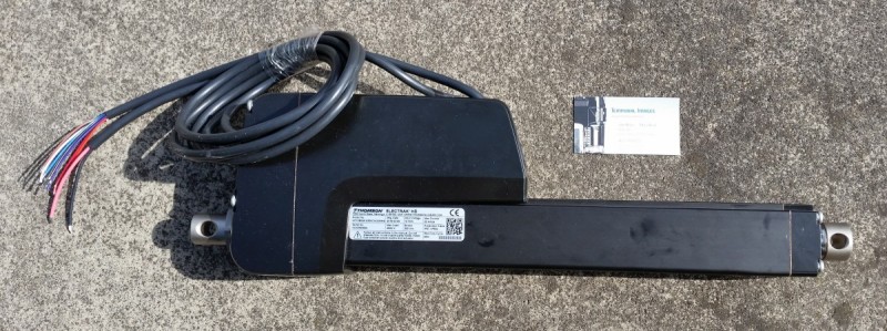
Thomson HD Linear Actuator
Return to Main Page
Links Page
Contact Us
The linear actuator can be controlled using CAN Bus and an Arduino processor board.
This approach is described here.


Thomson HD Electric Linear Actuator

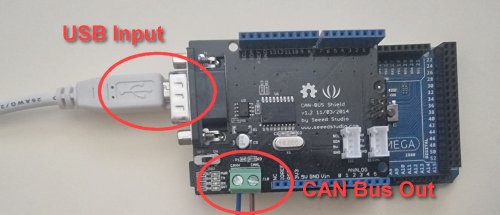
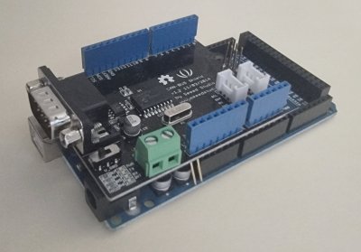
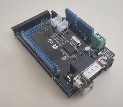
Arduino Mega 256 and Seeed Studios CAN Bus board.

For this case we used an Arduino Mega 2560 R2 processor board.
This has had a CAN Bus shield added to it. The shield used was from

Seeed Studio  (https://www.seeedstudio.com).

Specifically the shield used here was Version 1.2  (11/03/2014)

      https://www.seeedstudio.com/CAN-BUS-Shield-V2.html


Arduino and CAN Bus board connections

To program the micro-processor you will need to obtain some library files to handle
the J1939 CAN Bus interface. You should look at this link.

http://ard1939.com

to find out more, and obtain the necessary library files. We used the Arduino IDE
(Version 1.8.5) to compile and load the code into the micro-processor. One of the
files found on this web site is a demonstration file called
J1939_Gateway.zip. We
used this as the basis to produce a test program able to operate the actuator.
The modified version is available here.

http://www.temporal.com.au/J1939_Gateway_Actuator.zip

If you compile this code and run it within the Arduino IDE you can use the Serial
Monitor window to enter simple commands to move the actuator.

s   =   Initiate network scan
0   =   Move #0 50 mm (reset motion flag)
1   =   Move #1 50 mm
2   =   Move #2 100 mm
3   =   Move #3 200 mm

The code should be sufficient for anyone to add additional commands or alter
the commands already available.


Videos

Thomson HD Linear Actuator 12 volt 2 amp Power Supply

Thomson HD Linear Actuator 12 volt 20 amp Power Supply

CAN Bus USB Interface Board LED Activity

Screen Display for the J1939 Demo Application


Copyright (C) 2022 Temporal Images Email Us Last Modified: 22nd June 2022